- About
- News
- Research
- Products
- Product archive
- Applications
- Support
- Surplus
- По-русски
- Eesti keeles
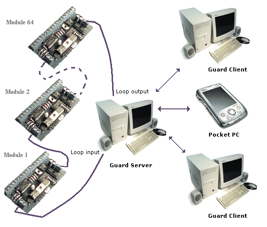
Guard system provides high-reliability guarding, alerting and calling signalization, could be applied for small as well as huge objects (for example: prisons, plants, power plants, multi-storey garages.) Maximal input zones: 2560, output zones: 1280.
System features:
Principle of operation:
All input-output devices are connected together serially with one-pair signal wire. First and last are connected to terminal or computer, thereby they form loop of modules. One loop consists of max 64 modules. Multi-loop center can operate max 5 loops (320 modules). Due work all connection are over system control: wire break does not cause system damage, place of rupture will be detected and reported to maintenance staff. Part of system will be alive even after multiple wire breaks or short circuits.Control center based on PC includes computer with operation system Microsoft Windows build on NT technology (NT4, 5, 5.10 or later) and graphical program named Guard.
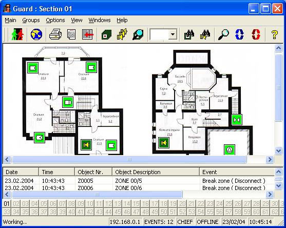
Interface converters transform PC RS232 interface into the current loop, case of multi-loop center, they allot pc interface to several destinations too. To increase system reliability it is highly recommended to use industrial computers or computers with energy consumption 50W and expanded range of working temperatures.
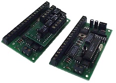
Type1: 8 inputs, 4 outputs, tamper
Type2: 5 inputs, 3 voltage measuring inputs, 4 outputs, tamper
Connection between modules: double-wire
Interface: current loop
Max modules amount in one loop: 64
Max range between neighbor modules: 500m
Current consumption: 50mA
Way of sensors connection: 2 resistors (2.2 kOhm) form the dual End Of Line resistance loops
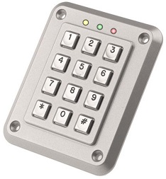
Keypad controller: 1 output, tamper
Used for set/unset guarding objects (zones, groups of zones or outputs)
Number of keys: 12 (0..9, *, #)
Outputs: 2 LEDs, buzzer, 1 universal
Inputs: tamper
Embodiments: Public environment, Industrial, Professional, Data entry
Current consumption: 50mA
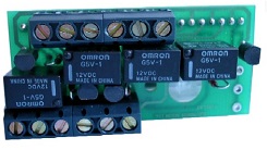
4th channel relay actuator for IO modules:
4th channel relay actuator for IO modules
Used for connecting external electrical devices (locks, sirens, strobes, etc) to the I/O module outputs.
Power supply unit:
Output voltage: 13.8V
Max output current: 1.4A
Tested parameters: output voltage, battery voltage, rectified voltage
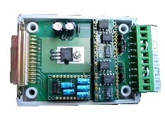
RS232 / Current Loop Converter:
Used for connecting I/O modules to the serial ports of the computer with Guard software installed
Card reader control module
Guard Server and Guard Client
Multi-storey garage: module is used for 4 boxes. Variant 1:
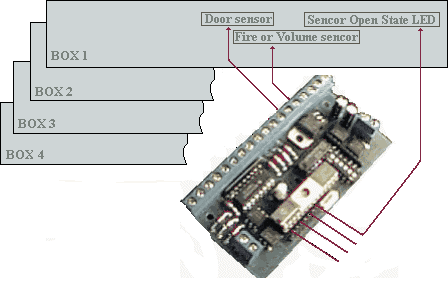
Keypads are placed in corridors. Owner of garage boxes uses keypad for set/unset his box. He closes the box door, makes sure that LED is in off state and using secure password sets box to guarding mode. Computer sends the operation result back to keypad: Set, Unset, Error.
Multi-storey garage: module is used for 4 boxes. Variant 2:
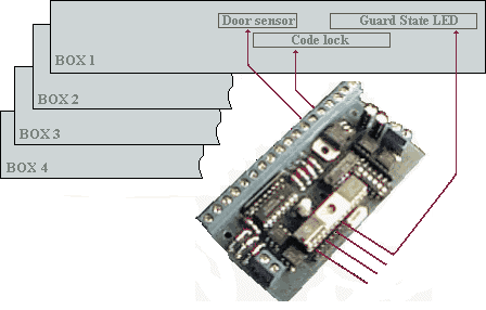
Owner sets/unsets his box with code lock, which is placed on each box. Computer confirms the operation turning on/off special Guard State LED.
Prison: module is used for 4 prison cells:
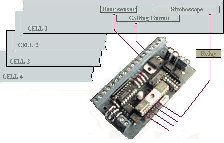
Duty officer sets / unsets chambers from control center. Pushing the Calling Button inside cell will send alert signal and turn stroboscope on, which is situated above cell's door, duty officer has to accept incoming alert, which will automatically turn stroboscope off.
Prison: module is used for corridor door control:
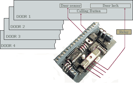
Duty officer open and close the door locks from control center. Pushing the Calling Button will send alert signal. Duty officer receives signal and gives command to open the door lock. Module opens the door lock, waits for programmed delay and becomes ready to close it. After closing the door, module closes the door lock.